HomeDefinitionPage 4
If you want to reduce the conducted common mode current into the VFD (which is what is needed to meet EMI requirements) then the best approach is to insert a common mode inductor in series with the input terminals and the motor drive and then connect capacitors to ground (typically between 0.1uF and 1uF) from each motor drive input terminal (on the source side of the common mode inductor) to chassis ground.
In terms of damping of HF CM current (and lowering of dv/dt spikes), it may also be noteworthy to highlight Yaskawa's use of 3-level-inverter and matrix-drive topologies. The former 3-level-inverter topology has long been used by Yaskawa in its low voltage drives whereas LV VFD drives generally use 2-level-inverter topologies; the latter matrix-drive topology has recently been commercialized by Yaskawa.
Using this direct drive motor will give a significant financial saving in electrical energy, with a pay back period under 12 Months, reduced maintenance as no power train required in most applications. The company can also claim carbon credits to offset the heating carbon debits incurred in the drying stage. I also think there are EU grants for this type of conversion. If you are not in the EU, the financial savings due to the high efficacy still justify the conversion.
If the 100% torque at 5% speed is what you require, then the variable frequency drive must be able of producing the additional voltage drop in the motor feeder cable and the output sine wave filter. Subject to the motor feeder length, the voltage drop at full load could be 10 to 15 volts and the sine wave filter may have even a higher voltage drop across it.
Power factor will increase vs. load. The minimum value is obtained at no-load and is around 0.2 because absorbed active power is minimum (only losses) and reactive power is high. As you increase the motor load, the p.f. will increase because active power increases and reactive power remains constant (it's not affected by load).
Category
AC Motor Control
Featured
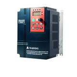
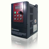
 This low voltage (single phase 220V, three phase 380V) variable frequency drive manufactured by Gozuk has compact design and integrated advanced technology ...
 Special magnetic flux vector control VFDs
Power range: single phase 1.5kW to 2.2kW, 3 phase 0.75kW to 400kW
Integrated RS485, Modbus-RTU communication protocol
32 ...
Active Front End (AFE) variable frequency drive has some harmonic filtering at the input to the VFD that is "programmable" on the fly. Basically, a microprocessor ...
An inverter duty motor can deal with the higher voltage spikes produced by VFDs also can run at very slow speeds without overheating. The general purpose motor ...
Multiple motors operation is quite common application. There are many applications like textile, printing etc where multi motor operation is very common. I ...
In summary, when using a VFD there are many benefits and cost saving possibilities for pumping applications in the irrigation sector. It is important to look ...
Recent
Increase the speed of a motor by VFD
VFD in Crane and Hoist Applications
VFD for Fire Pump Motors
Is it VFD the best solution to control pump?
3HP VFD, single phase to three phase VFD
Insulated bearings for electric machines
Control ABB VFD through RTD 250ohm directly on water temp
Variable frequency drive Preventive Maintenance
Large VFD trips with power supply by transformer
Induction motor power factor
Understanding VFD basics
Does the motor lifetime depend on the starts number & frequency?

