HomeFAQ
Considering the VFD, it can be mounted on top of the motor or there are also models that can be mounted separate to the motor, the variable frequency drive can be setup so that the pump can deliver constant flow or pressure. It would be a simple solution to vary the flow and keep you energy usage under control.
Sounds like a VFD still be the best option. It's important to choose the brand/series that best fits your application and environment and avoid adding the hidden problems.
The bearings in induction motors can benefit from insulated bearings where shaft currents are high and use the bearings as a route to earth. This I am sure you are aware. Most induction motors do not suffer with this problem however, those fed with variable frequency drives can and do. If you feel that your application would benefit from some form of protection, there are other solutions which have proven to be cheaper and more effective than insulated bearings and can be fitted with no requirement to remove the armature from the machine casing (and even the load).
Multiple motors operation is quite common application. There are many applications like textile, printing etc where multi motor operation is very common. I have seen many VFD manufacturers recommending multiple motor operation. Say in a textile loom, there could be scores of Motors running spinning pumps, godets, winders etc. If there are some 40 Motors of say 0.5 HP, then one can certainly go in for one single variable frequency drive of say 25 hp rating. That would be the best and most economical and practical solution.
Both AC and DC machines starting on variable frequency drives do not have a maximum number of start attempts over the life of the machine provided the variable frequency drive programming and protection mechanisms limits the amount of current drawn during the transient period to a reasonable (below 1.25 per unit) value.
Absolutely no, because from the terminal connections to control cards are rated for certain voltage level and PCB are have the EEPROM which is programmed for 380 V if the variable frequency drive is manufactured for 380V because the controls are incorporated to monitor the DC link circuit, if the supply voltage is increased, the DC link voltage will also be increased hence the VFD drive will trip on DC over volt. If the voltage is increased the amount of heat dissipation increases thus it requires big heat sink and ventilation fans thus requires the enclosure size to be increased better take a new variable frequency drive from a reputed brand.
In general, a very low-inductance load will increase the DC bus ripple current and increase heating of the capacitor bank. In general, using a general-purpose VFD with a NEMA design or inverter-rated motor should be no problem, but if you rig up an R-L load for testing purposes, make sure there's enough inductance. Otherwise you could damage the DC bus capacitors.
In the VFD (variable frequency drive) there are parameters called "Carrier Frequency" and "Auto-tuning", what is the effect of these parameters on improving the output waveform?
The auto-tuning function gives the VFD's vector control algorithm better than stock parameters to control the motor flux, and ultimately the output torque performance of the machine.
The auto-tuning function gives the VFD's vector control algorithm better than stock parameters to control the motor flux, and ultimately the output torque performance of the machine.
Now, apply your VFD-driven motor to the "load" motor shaft. Accelerate the VFD motor until the load motor is operating at synchronous speed. The closer you get to sync speed, the lower the real power will be. Since the applied voltage doesn't change, the real current must. At synchronous speed there will be no slip in the load motor. The rotor is spinning at the same speed as the rotating field. No lines of flux are being cut, no current is induced in the rotor. The only current that motor will draw is reactive current, correct?
Actually, there's a limit to how much the DRIVE can handle, and then there's a limit to what the dynamic braking resistor can handle. Generally, the manufacturer is going to size the DB resistor under what the VFD can take in continuously. Here I'll have to defer to the various VFD manufacturers. For your application where you need to test the VFD under full load current simply to verify that you've repaired it correctly, a motor running on commercial power is going to be your best bet.
One problem which I have discovered is with the hall sensor placement. if that is not correct/accurate then it caused problem. since I was trying to run the home made motor (24 slot 28 pole) which might have inaccuracies in sensor placement, might be the root cause of the problem.
I have worked in electric machine design and development for twenty years. When I was an undergraduate in the late 1980's, the study of electric machines as primary subject matter in the U.S. undergraduate EE curriculum was on the decline. At that time, I believe that my alma mater, Michigan Technological University was only one of 20 or so U.S. universities to have significant undergraduate course offerings in electric machines.
As an electrical person I can say that I have seen these problems and helped with wiring. The VFD (variable frequency drive) capacitive couples electricity to 'where it wants to go'. It wants to get back to the VFD. Here is best practice: Shielded motor cable tied to frame with 360-degree bonds at both motor and VFD, uninterrupted. (VFD, not cabinet).

Category
AC Motor Control
Featured
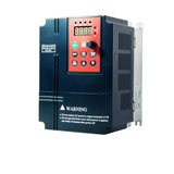 This low voltage (single phase 220V, three phase 380V) variable frequency drive manufactured by Gozuk has compact design and integrated advanced technology ...
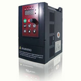
 Special magnetic flux vector control VFDs
Power range: single phase 1.5kW to 2.2kW, 3 phase 0.75kW to 400kW
Integrated RS485, Modbus-RTU communication protocol
32 ...
Active Front End (AFE) variable frequency drive has some harmonic filtering at the input to the VFD that is "programmable" on the fly. Basically, a microprocessor ...
An inverter duty motor can deal with the higher voltage spikes produced by VFDs also can run at very slow speeds without overheating. The general purpose motor ...
Multiple motors operation is quite common application. There are many applications like textile, printing etc where multi motor operation is very common. I ...
In summary, when using a VFD there are many benefits and cost saving possibilities for pumping applications in the irrigation sector. It is important to look ...
Special magnetic flux vector control VFDs
Power range: single phase 1.5kW to 2.2kW, 3 phase 0.75kW to 400kW
Integrated RS485, Modbus-RTU communication protocol
32 ...
Active Front End (AFE) variable frequency drive has some harmonic filtering at the input to the VFD that is "programmable" on the fly. Basically, a microprocessor ...
An inverter duty motor can deal with the higher voltage spikes produced by VFDs also can run at very slow speeds without overheating. The general purpose motor ...
Multiple motors operation is quite common application. There are many applications like textile, printing etc where multi motor operation is very common. I ...
In summary, when using a VFD there are many benefits and cost saving possibilities for pumping applications in the irrigation sector. It is important to look ...
Recent
Increase the speed of a motor by VFD
VFD in Crane and Hoist Applications
VFD for Fire Pump Motors
Is it VFD the best solution to control pump?
3HP VFD, single phase to three phase VFD
Insulated bearings for electric machines
Control ABB VFD through RTD 250ohm directly on water temp
Variable frequency drive Preventive Maintenance
Large VFD trips with power supply by transformer
Induction motor power factor
Understanding VFD basics
Does the motor lifetime depend on the starts number & frequency?