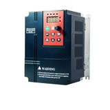
Torque limiter and VFD for motor safety control
Torque Limiters have a Mechanical Reason for being (many different Load Applications from Fluids, Gas, Slurries/Solids, etc.). Remember that Limiters can be used for both extremes Inertial Ramp UPs (or DOWNs) where "loss of a flywheel" means just as much as "locking up a flywheel" to a Mechanical Shaft being used to control something.
VFD Safety Control(s) are mostly Electrical & Magnetic, with a combination of things to Prevent a Device (VFD, Quick Blow Fuses, Overcurrent, Voltage Dips/Loss, etc.) from turning into Shrapnel, Catching on Fire, Exploding, Losing a Winding, which have nothing to with the actually Mechanical End of the Drive Unit as a Whole.
Worked on Motors that are 3(4) Series Pumps with over 25,000HP each (at 72KV), various Buck-Boost arrangements of Electrical-Hydraulic Motors (Crushers, Pipelines, etc) Starting at around 1200HP and 5KV (and up). I spent a short amount of time in a Steam Generating Plant (twin 1300 MW units running 720KV lines) where the fins on the Turbine Blades proved interesting IF EVER the Generator goes off in to Motoring Load (one December a sister plant went Off-line and triggered a Reflective Wave across two states). Turbine work has been mostly Co-Gen Mark V/VI units (or like) producing 150MW and higher depending on the Gas being used as Fuel.
Imagine a set of Series Pumps (each at 25,000HP) pump water (or water plus solids) UP a vertical pipe (few 100 feet). What happens IF that variable frequency drive fails? What happens if the Mechanical Shaft driving the Pump fails, what will the VFD know to do? What happens if the Characteristic Load of the water + solids meets up with Major resistance to Flow (plugged, valve failed and closed shut,... ) is the VFD going to do something here (if so what) OR is the Torque Limiter going to do something here (if so what) OR are they going to independently going to work together to hold the vertical column of water in place UNTIL a relief/return Line is opened and Pressure is removed from the Pump Discharge.
We have the same thing with Fans, Conveyors, Elevators, Mechanical Drives, etc. The Torque Limiter can also FAIL (or fail intermittently as a Cam Driven unit), which leaves the variable frequency drive (or other) to sense what is happening. Chain drives are notorious for this type of thing which would NOT be seen on the variable frequency drive, but would show up in the Operation of a Clutch type Torque Limiter.
How is it that you're attempting to remove protective devices between the Motor and the VFD? By Code, you have a minimum of Local Fused Disconnect (or like) or Switch if you're within so many feet and line-of-sight of a Mains Disconnecting means.
How do you "derate" the Short Circuit Current needed by the Motor(s)?
MOVs(or newer Power Electronic gating devices) are on the VFD side and still between the Motor and the VFD, even IF housed in the VFD? You have these in your variable frequency drive?
How do you account for testing the VFD without the Motor attached?
Testing the Motor without the VFD providing KW and VARs to the Load?
IF you use large induction Motors AND need Capacitors to either Line Balance or offset the Vars loading, THEN how do you disconnect the Capacitors from the Motor circuit without some Relay Protective Circuits?.
One other component is that we have both 3 Wire (delta) systems in plants and 4 Wire (start-wye) systems in plants. Could you describe what you're doing with Ground currents in each IF you have no protection (or grounding) at the Motor?
At some point the motor has to be disconnected from the variable frequency drive. Usually the motor is equipped with fuses and a contactor, but in very large systems like the amount of kinetic energy stored in the load and all the magnetic energy stored in the motor amount to a fabulous total that somehow has to be dissipated. If you just open the circuit there is going to be arcing and all sorts of collateral damage. To eliminate the need for any maneuvering or protection devices between the VFD and the motor I've been trying to use VFDs rated for motor protection, but those are far less common and on the expensive side.


